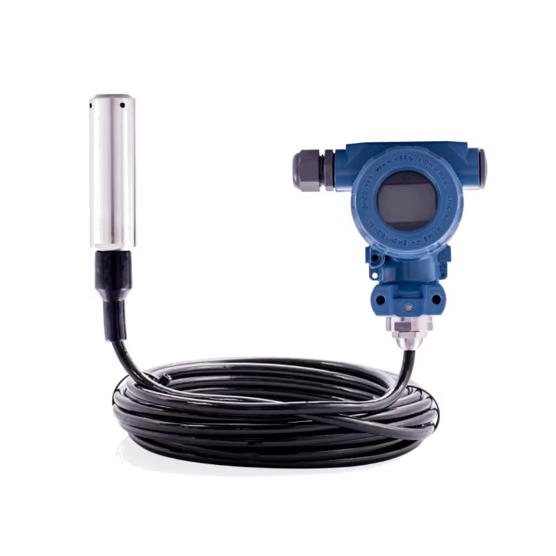
Lightning level transmitter is a commonly used transmitter in the automation of water industry, which is widely used in the measurement and control of water level in the fields of industrial water treatment engineering, water level of building water tower, environmental protection, water conservancy, power plant, urban water supply and drainage, hydrological exploration and so on.Simple installation, easy to use.
Working Principle
The working principle of the lightning level transmitter is that the pressure acts directly on the diaphragm of the sensor, so that the diaphragm produces a micro-displacement proportional to the medium pressure, so that the sensor's resistance changes, and the electronic circuit detects this change and converts the output of a standard signal corresponding to this pressure.
Characterization
1. Sensor: can feel the prescribed measurement and in accordance with certain laws into a usable output signal device or device.Usually there are sensitive components and conversion components.
① sensitive element refers to the sensor can be measured directly (or response) in the part.
② conversion element refers to the sensor can be more sensitive elements feel (or response) of the north side of the amount converted into is with the transmission and (or) measurement of the electrical signal part.
③ When the output is a prescribed standard signal, it is called a transmitter.
2. Measuring range: the range of the measured value within the permissible error limits.
3. range: the algebraic difference between the upper and lower limits of the measurement range.
4. accuracy: The degree of agreement between the measured result and the true value of the quantity being measured.
5. repeatability: the degree of agreement between the results of multiple successive measurements of the same measured quantity under all of the following conditions:
6. resolution: the smallest amount of change in the measured quantity that can be detected by the transducer within a specified measurement range circle.
7. Threshold: the minimum amount of change in the measured quantity that can produce a measurable change in the output of the sensor.
8. Zero: The state in which the absolute value of the output is minimized, such as equilibrium.
9. Excitation: The external energy (voltage or current) applied to the sensor to enable it to function properly.
10. Maximum Excitation: The maximum value of excitation voltage or current that can be applied to a transducer under in-city conditions.
11. Input Impedance: The impedance measured at the input of the sensor when the output is short-circuited.
12. Output: The amount of electricity produced by a sensor as a function of the applied measurement.
13. Output impedance: the impedance measured at the output of the sensor when the input is short-circuited.
14. Zero Output: The output of the transducer when the applied measured value is zero under city conditions.
15. hysteresis: the maximum difference that occurs in the output as the measured value increases and decreases within a specified range.
16. hysteresis: the time delay between a change in the output signal and a change in the input signal.
17. drift: in a certain time interval, the sensor output is finally measured unrelated to the amount of unwanted changes.
18. Zero drift: in the specified time interval and room conditions when the zero output changes.
19. sensitivity: the ratio of the increment of the sensor output to the corresponding increment of the input.
20. sensitivity drift: the change in the slope of the calibration curve due to a change in sensitivity.
21. thermal sensitivity drift: sensitivity drift due to changes in sensitivity.
22. Thermal Zero Drift: The drift of the zero point due to changes in ambient temperature.
23. Linearity: the degree to which a calibration curve agrees with a specified limit.
24. Philosophy linearity: the calibration curve and a specified degree of deviation from a straight line.
25. long-term stability: the sensor in the specified time can still maintain the ability not to exceed the allowable error.
26. intrinsic credentials: in the absence of resistance, the sensor's free (without external force) oscillation credentials.
27. Response: The characteristic of the measured change in output.
28. Compensated Temperature Range: The temperature range compensated for by keeping the sensor in range and zero balance within specified limits.
29. Creep: The change in output over a specified period of time when the measured machine much have environmental conditions remain constant.
30. Insulation Resistance: If not otherwise specified, the resistance measured between specified insulating parts of a transducer when a specified DC voltage is applied at room temperature.